ByJohn A
Zig Zag Grounding Transformer: Design, Operation, and Practical Uses
Electrical distribution systems need a dependable path for fault current so protective equipment can detect abnormal conditions and disconnect affected circuits. A properly designed grounding arrangement helps control fault voltages, supports protection equipment, and reduces the risk associated with insulation failures. In systems where a neutral point is unavailable or needs additional grounding support, a zig zag grounding transformer can provide a practical connection between the electrical network and earth.
Why Grounding Matters in Electrical Systems
Grounding provides a controlled electrical path between selected parts of a power system and earth. Under normal conditions, this connection may carry little or no current. During a line-to-ground fault, however, the grounding arrangement allows fault current to return through a defined path.
Without an appropriate grounding method, a system can experience unstable voltages, excessive transient conditions, or difficulty detecting ground faults. The grounding design also affects the ratings and operating characteristics of protective devices.
The selected grounding method depends on factors such as system voltage, available fault current, neutral configuration, equipment ratings, and the required protection scheme. Industrial plants, utility networks, generators, and distribution systems may use different arrangements according to their electrical characteristics.
What Is a Zig Zag Grounding Transformer?
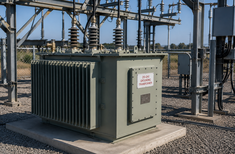
A zig zag grounding transformer is a transformer designed primarily to create a neutral point for grounding an electrical system. It is commonly used on three-phase systems that do not have an accessible neutral connection.
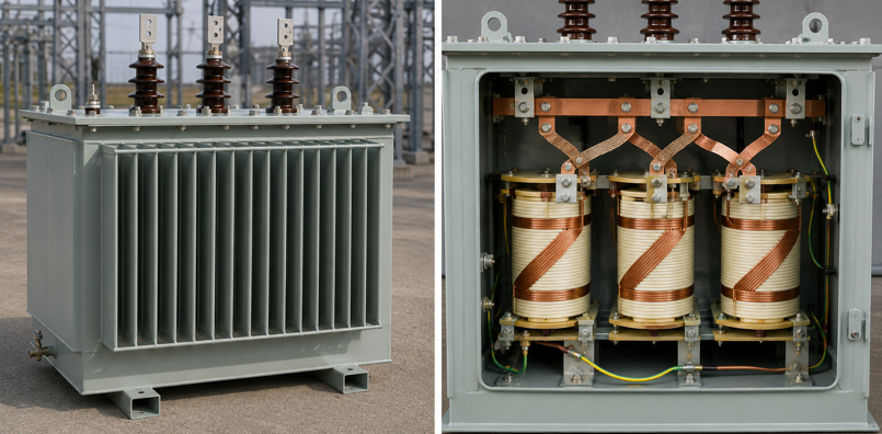
Its winding arrangement differs from that of a conventional two-winding transformer. The windings are divided and interconnected so that the transformer presents a suitable path for zero-sequence current while maintaining the normal three-phase operation of the connected system.
During balanced three-phase operation, the magnetic effects associated with the three phases largely cancel within the transformer. During a ground fault, the zero-sequence components produce a different magnetic condition, allowing current to flow through the grounding arrangement.
This characteristic makes the equipment useful for systems requiring a grounding point without providing a conventional secondary power supply.
How the Zig Zag Arrangement Works
The winding configuration is the defining feature of this transformer. Each phase is associated with winding sections arranged across different magnetic paths. These sections are interconnected in a manner that creates the desired neutral point.
Under balanced conditions, the currents in the three phases have a vector relationship that keeps the transformer from behaving like a conventional load transformer. The unit therefore consumes relatively little power under normal operating conditions, although losses still occur.
During a single-line-to-ground fault, the current components no longer remain balanced. Zero-sequence current can pass through the transformer and return through the grounding connection. The impedance of the transformer limits the magnitude of this current according to the system design.
The grounding arrangement therefore has two related functions: establishing a neutral reference and providing a controlled route for fault current.
Grounding a Transformer in a Distribution System
Grounding a transformer requires more than simply connecting equipment to an earth conductor. Engineers must determine the intended grounding method, fault-current level, grounding impedance, insulation requirements, and protection settings.
A grounding transformer may be connected to a resistor or other impedance device when the system requires fault-current limitation. The grounding resistor controls the amount of current that can flow during a ground fault. This can reduce equipment stress while still producing enough current for protective relays to recognize the fault.
The grounding connection also needs suitable mechanical and electrical protection. Conductors, terminals, enclosures, and associated equipment must be rated for the expected fault conditions and installed according to applicable electrical standards.
Ground Transformer Selection Factors
Selecting a ground transformer involves several electrical parameters. Voltage rating is one of the first considerations because the transformer must match the system on which it will operate.
The required ground-fault current is another major factor. A transformer intended for a high-current grounding arrangement will have different specifications from one designed for a resistance-grounded system with limited fault current.
Other considerations include:
- System line-to-line voltage
- Ground-fault current requirement
- Continuous neutral current
- Short-time current rating
- Zero-sequence impedance
- Thermal withstand capability
- Insulation level
- Installation environment
- Grounding resistor requirements
- Protective relay characteristics
The transformer should be selected as part of the complete grounding system rather than as an isolated component.
Role of the Zigzag Transformer During Faults
The main electrical purpose of a zigzag transformer is to provide a low-impedance path for zero-sequence current when the system experiences a ground fault.
For example, a fault involving one phase and earth creates an unbalanced condition. The resulting zero-sequence current can flow through the grounding transformer and associated grounding equipment. This gives protection systems a measurable fault current that can be detected by appropriate relays.
The transformer does not normally supply useful load power to downstream equipment. Its role is associated mainly with grounding and fault-current management.
The impedance selected for the transformer influences the available fault current. A lower impedance generally permits higher fault current, while additional impedance can limit the current. The appropriate value depends on the protection and safety requirements of the electrical network.
Transformer Grounding and Protection Coordination
Transformer grounding must work together with the protection system. Ground-fault relays, circuit breakers, fuses, current transformers, and other protective equipment need to operate according to the expected fault-current range.
If the grounding impedance is too high, a fault may produce insufficient current for reliable protection detection. If it is too low, fault current may become unnecessarily large and place greater mechanical and thermal stress on electrical equipment.
Protection engineers therefore examine the grounding transformer characteristics alongside relay settings and system fault calculations. Coordination helps ensure that the affected section can be disconnected without unnecessarily interrupting other parts of the network.
Installation Considerations
Physical installation can affect the performance and maintenance of the grounding equipment. The transformer should be installed in an appropriate location with adequate clearance, ventilation, and access for inspection.
Connections between the transformer, grounding resistor, neutral point, and earth system should be designed to withstand expected fault conditions. Cable routing should also reduce unnecessary mechanical stress and allow technicians to inspect connections.
Outdoor installations may require suitable enclosures and environmental protection. Indoor installations need adequate ventilation and sufficient working space around the equipment.
The grounding electrode system is equally significant. Its resistance and physical condition can influence the overall grounding performance, so it should be inspected and maintained according to the applicable installation requirements.
Maintenance and Inspection
Grounding equipment can remain electrically quiet for long periods, which means routine inspection is easy to overlook. Yet its availability is particularly valuable during abnormal operating conditions.
Maintenance programs may include visual inspection, checking physical connections, examining signs of overheating, testing insulation where appropriate, and inspecting grounding conductors and associated resistors.
Thermal damage, corrosion, loose connections, cracked insulation, or damaged enclosures should be addressed before the equipment is required during a fault.
Testing should follow the manufacturer’s instructions and the applicable electrical standards. System shutdowns may be necessary for certain inspection and testing procedures.
See also: How Custom Apparel Businesses Scale with DTF Transfers
Where These Transformers Are Commonly Used
Grounding transformers are useful in electrical networks where a neutral connection is not naturally available. They may be found in industrial distribution systems, renewable-energy installations, generator systems, utility networks, and medium-voltage applications.
Their use is particularly relevant when engineers need to establish a defined neutral point while maintaining a three-phase system without adding a conventional power-transformer secondary winding.
The final configuration depends on the system’s voltage, fault-current requirements, protection philosophy, and grounding method.
Final Considerations for System Designers
A zig zag grounding transformer is a specialized component that supports neutral creation and controlled ground-fault current in three-phase electrical systems. Its winding arrangement allows zero-sequence current to follow a designed path during ground faults while having limited influence on normal balanced operation.
Good system design starts with a clear understanding of the network’s fault behavior. Voltage level, required fault current, grounding impedance, protection settings, thermal ratings, and installation conditions should all be considered together.
Correct sizing and installation can help a grounding system provide a predictable fault-current path and support reliable operation of protective equipment. Because grounding systems directly affect electrical safety and fault behavior, design, installation, testing, and maintenance should be performed by qualified electrical professionals in accordance with applicable standards.